
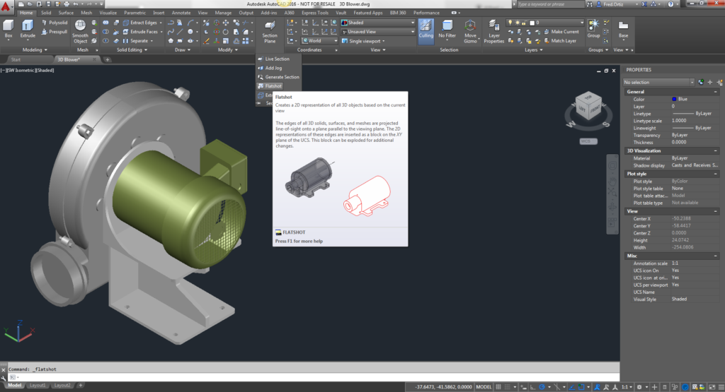
AutoCAD drawings are rarely completed simply by drawing lines, circles etc. Most likely you will need to Modify these basic drawing objects in some way in order to create the image you need. AutoCAD provides a whole range of modify tools such as Move, Copy, Rotate and Mirror. As you can see, the command names are easily understandable. However, the way these commands work is not always obvious. This tutorial is designed to show you how all of the Modify commands work.
An annotation object is any object that participates in annotation scaling. The specific type of annotation, its appearance, and other characteristics are determined by user-editable values on the Tool Properties worksheet, which is accessed from the context menu of the particular tool. The following are annotation objects created by AutoCAD:
-
-
- Text
- MText
- Dimensions
- Leaders
- Block References
- Hatches
-
Layers are the primary method for organizing the objects in a drawing by function or purpose. Layers can reduce the visual complexity of a drawing and improve display performance by hiding information that you don’t need to see at the moment. Blocks are the collection of geometries that act as a single object and they can be used in a drawing repetitively. The blocks which are used in the drawing are called block references and if you modify the block all its references change automatically.
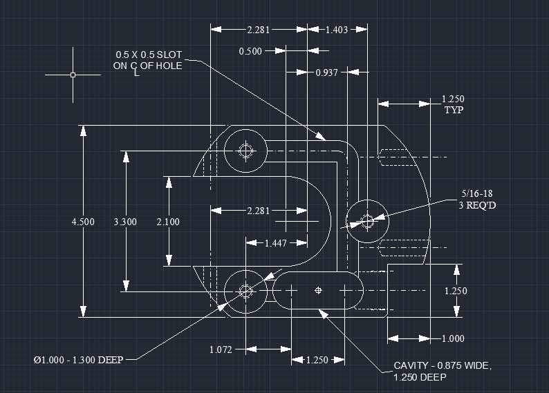
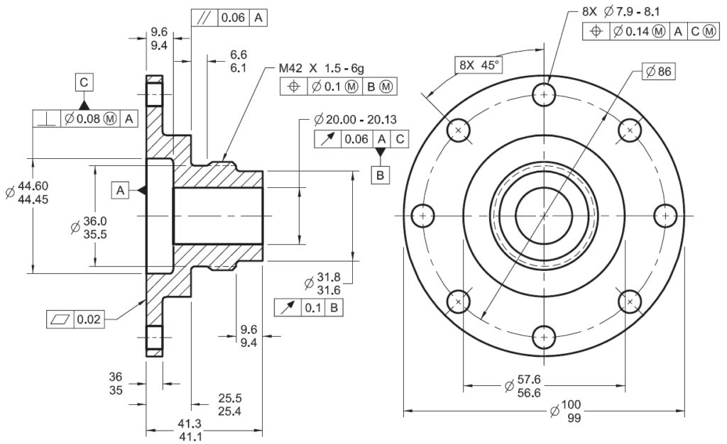
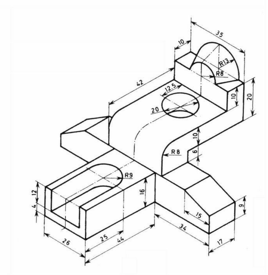
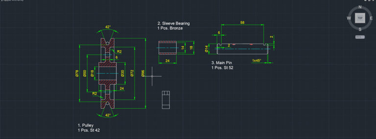
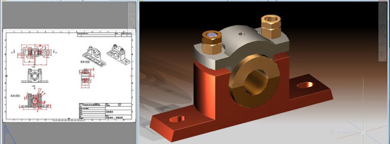
Orthographic projection, common method of representing three-dimensional objects, usually by three two-dimensional drawings in each of which the object is viewed along parallel lines that are perpendicular to the plane of the drawing. For example, an orthographic projection of a house typically consists of a top view, or plan, and a front view and one side view (front and side elevations).
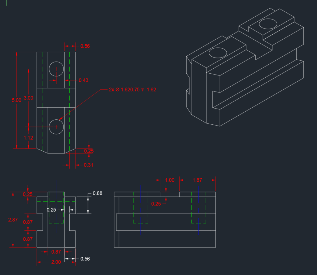
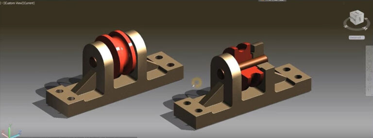
A 2D isometric drawing, which may be created from an isometric projection, is a flat representation of a 3D isometric projection. This method of drawing provides a fast way to create an isometric view of a simple design. Distances measured along an isometric axis are correct to scale. But because you are drawing in 2D, you cannot expect to extract other 3D distances and areas, display objects from different viewpoints, or remove hidden lines automatically.
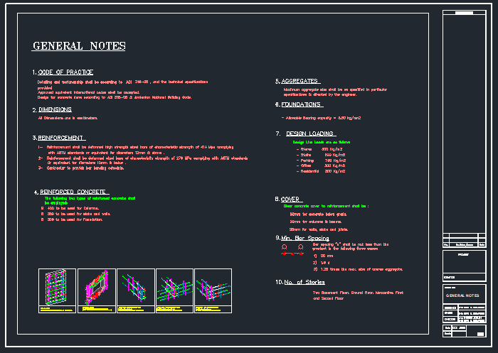
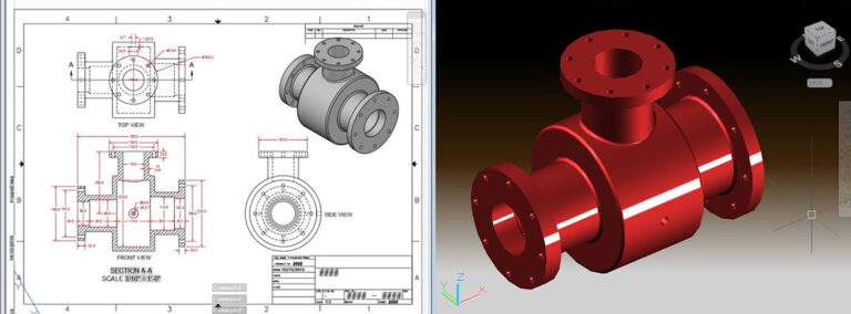
A layout is a 2D working environment for creating drawing sheets. The area within a layout is called paper space, where you can add a title block, display scaled views of model space within layout viewports, and create tables, schedules, notes, and dimensions for your drawing.

"I have learned AutoCAD and Catia here. Sir taught in very easy understandable method. We dont need to worry about the basics also. Everything will be taught from there step by step in a process"

"Get Trained on AutoCAD and Solidworks ..Got my Dream Job..Thank You"

One of the best online Platform to Learn CAD courses.. Got trained in NX CAD and Creo 7.0 .. Absolutely Best training, Doubts are clarified on the class itself.. I recommend you guys to Join here...

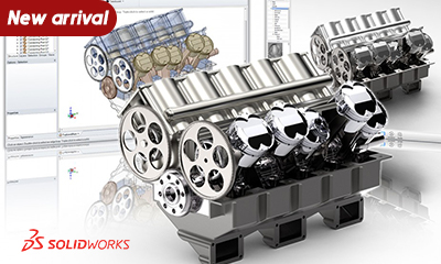
Solidworks 2020 Masterclass
This course will help you to create parametric models and this is for absolute beginners who have never done any CAD courses before.
Revit MEP - Basic to Advanced
Revit MEP allows you to design different systems such as Mechanical, Electrical, Plumbing , Security and so on along with you can create your own families.

Catia V5 - Basic to Advanced
A most popular 3D modelling software in both Automotive and Aerospace related components, with advanced sheet-metal and surface modelling techniques.